아두이노 스펙트럼 쉴드는 두개의 채널(좌우) 오디오 입력을 채널당 7개 밴드로 나눌 수 있습니다. 즉, 사운드 입력을 통해서 LED, 모터, 펌프, 릴레이 등을 제어할 수 있는 신기방기한 제품입니다.
같은 제품은 아니지만 동일한 칩을 이용한 예제를 보시면 대략 어떠한 제품인지 알 수 있을것입니다! 일단 영상한번 보시죠~
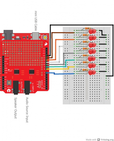
아두이노 코드 //Declare Spectrum Shield pin connections #define STROBE 4 #define RESET 5 #define DC_One A0 #define DC_Two A1
//Define LED connections on the Arduino/Shield int LED[] = {7, 8, 9, 10, 11, 12, 13};
//Define spectrum variables int freq_amp; int Frequencies_One[7]; int Frequencies_Two[7]; int i;
/********************Setup Loop*************************/ void setup() { //Set LED pin configurations for(i=0; i<7; i++) { pinMode(LED[i], OUTPUT); digitalWrite(LED[i], LOW); } //Set spectrum Shield pin configurations pinMode(STROBE, OUTPUT); pinMode(RESET, OUTPUT); pinMode(DC_One, INPUT); pinMode(DC_Two, INPUT); digitalWrite(STROBE, HIGH); digitalWrite(RESET, HIGH); //Initialize Spectrum Analyzers digitalWrite(STROBE, LOW); delay(1); digitalWrite(RESET, HIGH); delay(1); digitalWrite(STROBE, HIGH); delay(1); digitalWrite(STROBE, LOW); delay(1); digitalWrite(RESET, LOW); }
/**************************Main Function Loop*****************************/ void loop() { Read_Frequencies(); Graph_Frequencies(); delay(50); }
/*******************Pull frquencies from Spectrum Shield********************/ void Read_Frequencies(){ //Read frequencies for each band for (freq_amp = 0; freq_amp<7; freq_amp++) { Frequencies_One[freq_amp] = analogRead(DC_One); Frequencies_Two[freq_amp] = analogRead(DC_Two); digitalWrite(STROBE, HIGH); digitalWrite(STROBE, LOW); } }
/*******************Light LEDs based on frequencies*****************************/ void Graph_Frequencies(){ for( i= 0; i<7; i++) { if(Frequencies_Two[i] > Frequencies_One[i]){ digitalWrite(LED[i], HIGH); delay(Frequencies_Two[i]); digitalWrite(LED[i], LOW); } else{ digitalWrite(LED[i], HIGH); delay(Frequencies_One[i]); digitalWrite(LED[i], LOW); } } }
Description: The Spectrum Shield enables your Arduino with the capability of splitting a stereo audio input into 7-bands per channel. You can then read the amplitude of each channel using the ADC on your Arduino allowing you to control everything from LEDs to motors, pumps to relays, or even fire, all with sound. With this shield you will be able to have almost any project be able to react to music or sound! The Spectrum Shield features the MSGEQ7 graphic equalizer display filter. Two of these ICs allow you to split a stereo audio input into 7-bands (per channel) and read the amplitude of each using the ADC on your Arduino. The shield is populated with two 1/8" stereo jacks (like you would find on a pair of headphones). One serves as a stereo input and the other is a pass-through output which allows you to connect the Spectrum Shield in-line between your audio source and your stereo system without interruption. This revision of the Spectrum Shield has been updated to the Arduino R3 layout but still requires you to solder on your own headers (check the Recommended Products section below). This shield can be used to create sound visualizers, detect patterns in music or add sound activation to your microcontroller projects. Note: This product is a collaboration with Ben Moyes of Bliptronics. A portion of each sales goes back to them for product support and continued development. Documents:
|